Sunday, February 21, 2010

Wireless LAN Professionals - Podcast series

I don't know if everyone is aware that Keith Parsons has a great weekly wireless podcast - each segment is chock full of great wireless related information.

The second in the series was with Marcus Burton regarding his recent Wireless Arbitration white paper.  It was an awesome technical deep dive into how stations access the shared wireless medium. 002 WLW – 802.11 Client Arbitration / Mgmt, Ctrl, Data Planes 

There will be a segment soon from Devin Akin - where he does a deep dive into the technical aspects of wireless QoS.  I can't wait!  Keith and I recorded a segment this weekend about my experiences sitting the CCIE Wireless lab - it will come out in a few weeks. I think he said it will be episode 9.

Visit Keith's site http://wirelesslanprofessionals.com/ and subscribe to the weekly podcast!

Delicious Tags

I'm going to try to keep my shortcuts to good articles all in one place. @etherealmind recommended that I start using delicious, so I've started saving CCIE Wireless related shortcuts there.  I think it will make it easier to find a particular "how-to" without trying to find the blog article where I link to the document

http://delicious.com/jenniferlucille

Thursday, February 18, 2010

Autonomous Bridge Link with multiple VLANs

So I did some digging just now to find a document from Cisco's site that covers a bridge link with multiple VLANs, and what do you know - I found a doc that I hadn't ever seen before.

Using VLANs with Cisco Aironet Wireless Equipment 


I knew I was in the right place when I saw this network diagram: LINK 


Important notes from this document:

When you install access points, only assign the infrastructure SSID when you use an SSID on:

  • workgroup bridge devices
  • repeater access points
  • non-root bridges
It is a misconfiguration to designate the infrastructure SSID for an SSID with only wireless laptop computers for clients, and causes unpredictable results.
In bridge installations, you can only have one infrastructure SSID. The infrastructure SSID must be the SSID that correlates to the Native VLAN.

In order to encrypt data that passes over the radio link, apply encryption to only the SSID of the Native VLAN. That encryption applies to all other VLANs. When you bridge, there is no need to associate a separate SSID with each VLAN. VLAN configurations is the same on both the root and non-root bridges.

Because interface BVI 1 is associated to the subinterface of the Native VLAN, the IP address assigned to interface BVI 1 must be in the same IP subnet as other infrastructure devices on the network (i.e. interface SC0 on a Catalyst switch that runs CatOS.) 


**Also found some discussion online about IP addresses and subinterfaces - the consensus was that the BVI interface should be the only one with an IP address applied, and all the subinterfaces operate at L2 only, so they shouldn't have any IP address information configured on them.

** from what I can tell - enabling voice optimization on an SSID in IOS is simple via the GUI, but it takes forever for the screens to refresh - I configured it this way & then went to the CLI to see what the output was..

Well, clicking that one Voice Optimized button sure adds a lot at the console:

 dot11 qos class background local
    cw-min 6
    fixed-slot 10
 !
 dot11 qos class video local
    cw-max 4
    fixed-slot 3
    transmit-op 0
 !
 dot11 qos class voice local
    cw-max 3
    transmit-op 0
    admission-control
    admit-traffic narrowband max-channel 75 roam-channel 6
 !
 dot11 qos class background cell
    cw-min 8
    fixed-slot 12
 !
 dot11 qos class best-effort cell
    cw-min 6
    fixed-slot 5
 !
 dot11 qos class video cell
    cw-min 4
    cw-max 6
    fixed-slot 5
    transmit-op 0
 !
 dot11 qos class voice cell
    cw-max 3
    transmit-op 0
    admission-control 

I think this line was added too:
dot11 phone dot11e 

Sunday, February 14, 2010

Audio Notes

Don't know if *anyone* will find this of any value.. but I made some audio tracks on Cisco/WLAN/Voice/QoS to listen to this week.. My weak spots is definitely WLAN QoS - so since I have some long car trips coming up next week, I thought I'd put that time to good use.  Link to the MP3s: http://bit.ly/cFz7wU

It isn't a podcast, just me reading through the 7921 deployment guide (which was written very poorly) and some sample questions from Cisco's site on the Implementing Cisco Unified Wireless Voice Netorks course (IUWVN) and chapter two from the Voice over Wireless LAN 4.1 Design Guide.  Sometimes it helps me to get it to sink in if I write it, say it and hear it many many times.

Wednesday, February 10, 2010

The old 4.x way of doing AP Groups and WLAN Override

Things have changed a lot since 4.2, but for the lab - time is standing still with the 4.2 code.  Don't forget that you'll be expected to do things as the used to be done, not as they are now in 6.0 code..


In a typical deployment, all users on a WLAN are mapped to a single interface on the controller. Therefore, all users associated with that WLAN are on the same subnet or VLAN. However, you can override this default WLAN setting to distribute the load among several interfaces or to group users based on specific criteria such as individual departments (for example, marketing) by creating access point groups (formerly known as site-specific VLANs). Additionally, these access point groups can be configured in separate VLANs to simplify network administration.

Using the CLI to Configure WLAN Override
Use these commands to configure the WLAN override feature for a specific access point using the controller CLI.
1. To enable or disable the WLAN override feature for a specific access point, enter this command:
config ap wlan {enable | disable} {802.11a | 802.11b} Cisco_AP
2. To define which WLANs you want to transmit, enter this command:
config ap wlan add {802.11a | 802.11b} wlan_id Cisco_AP 

and the old way of doing selective SSIDs from the access points - WLAN Override:

Configuring WLAN Override
By default, access points transmit all defined WLANs on the controller. However, you can use the WLAN override option to select which WLANs are transmitted and which are not on a per access point basis. For example, you can use WLAN override to control where in the network the guest WLAN is transmitted, or you can use it to disable a specific WLAN in a certain area of the network.

Using the CLI to Create Access Point Groups
To create an access point group using the CLI, enter this command:
config ap group-name group_name
To assign an access point to an access point group using the CLI, enter this command:
config ap group-name group_name ap_name

Color coded QoS chart from the Voice over Wireless LAN 4.1 Design Guide

I like the QoS  charts that are in this chapter of the design guide, but the chart runs of the page and isn't color coded like the nice QoS charts from Cisco Live BRKRST-2500 Campus QoS Design.


The LWAPP AP and WLC perform QoS baseline conversion, so that WMM values as shown below are mapped to the appropriate QoS baseline DSCP values, rather than the IEEE values.
From ccie(w)

In cases where the AP is translating CoS values, autonomous APs for example, the translation shown is below:

From ccie(w)


WMM uses the 802.1p classification scheme developed by the IEEE (which is now a part of the 802.1Q-2005 specification).  This classification scheme has eight priorities, which WMM maps to four access categories: AC_BK, AC_BE, AC_VI, and AC_VO. These access categories map to the four queues required by a WMM device.
 
From ccie(w)


... It is generally recommended that the Per-User Bandwidth Contracts settings be left at their default values, and that the IEEE 802.11 WMM features be used to provide differentiated services. For WLANs using a given profile, the IEEE 802.1P classification in that profile controls two important behaviors:
  • Determines what class of service (CoS) value is used for packets initiated from the WLC.  The CoS value set in the profile is used to mark the CoS of all LWAPP packets for WLAN using that profile. So a WLAN with a platinum QoS profile, and the IEEE 802.1P mark of 6, will have its LWAPP packets from the ap-manager interface of the controller marked with CoS of 5. The controller adjusts the CoS to be compliant with Cisco QoS baseline recommendations. The reason why it is important to maintain the IEEE CoS marking in the configuration is covered in the next point. If the network is set to trust CoS rather a DSCP at the network connection to the WLC, the CoS value determines the DSCP of the LWAPP packets received by the AP, and eventually the WMM classification and queuing for WLAN traffic, because the WLAN WMM classification of a frame is derived from the DSCP value of the LWAPP packet carrying that frame.
  • Determines the maximum CoS value that can be used by clients connected to that WLAN.
    The IEEE 802.1P classification sets the maximum CoS value that is admitted on a WLAN with that profile. WMM voice traffic arrives with a CoS of 6 at the AP, and the AP automatically performs a CoS-to-DSCP mapping for this traffic based on a CoS of 6. If the CoS value in the WLC configuration is set to a value less than 6, this changed value is used by the WLAN QoS profile at the AP to set the maximum CoS marking used and therefore which WMM AC to use. The key point is that with the Unified Wireless Network, you should always think in terms of IEEE 802.11e classifications, and allow the Unified Wireless Network Solution to take responsibility for converting between IEEE classification and the Cisco QoS baseline.
This is the chart from the QoS class at Cisco Live 2009 [QoS on Cisco switches]:

From ccie(w)


There was also a nice colorized chart explaining the packet tagging translation that occurs to and from the client device at the controller.  This image is from BRKAGG-2013 Design and Deployment of Voice over Wireless LAN.

From ccie(w)

Monday, February 8, 2010

Configuring Access Layer QoS for Voice on Cisco Catalyst 6500 with Cisco IOS SW

mls qos
! -- turns QOS on for the whole switch
mls qos map cos-dscp 0 8 16 24 32 46 48 54
! -- maps COS to DSCP using the new standards of CS3 for signaling.
interface fastethernet 5/1
! -- the interface of course
switchport mode access
! -- disable trunking
switchport voice vlan 111
! -- enable trunking when CDP detects a phone. This is called DTP or Dynamic Trunking Protocol.
switchport access vlan 11
! -- set the VLAN for the phones built in switch for the PC on the other side of the phone or for the PC when no phone is detected.
spanning-tree portfast
! -- disable the slow detection of loops with spanning tree. This is a single endpoint and should never have a switch connected to it.
mls qos trust cos
! -- trust the COS of the traffic from the phone
mls qos trust extend cos 0
! -- mark all traffic from the PC to COS 0 no matter what the PC says it should be.

------------------------------

In depth configuration of a "full trust" policy for phones connected to a 6500:

Excerpt below taken from: Configuring Access Layer QoS for Voice on Cisco Catalyst 6500 with Cisco IOS SW

CONFIGURATION OVERVIEW

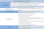
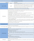
This sample configuration implements one of several methods to provide QoS at the access layer of an IP Communications deployment. Specifically this configuration is limited to a "full trust" policy on the switch interface. The "full trust" policy assumes a Cisco IP Phone (from Table 3) will be connected to the port to which this policy is applied, as the IP phone is responsible for remarking the PC traffic to CoS = 0. If a PC is instead directly connected to an interface with "full trust" policy, and its traffic is untagged, the switch marks the traffic CoS = 0. However, if the directly connected PC is marking its traffic with a CoS value, the switch accepts it because the port is configured to trust any received CoS. A "conditional trust" policy may be used as an alternative to reduce this possible risk. Though supported on several other Cisco Catalyst switch platforms, Cisco IOS Software for the Cisco Catalyst 6500 does not currently support the mls qos trust device cisco-phone command, which is the simplest method to implement a "conditional-trust" policy. Please see other Cisco documentation for more information regarding "conditional trust" policy configuration.

For the Cisco Catalyst 6500 to act as an access switch for a Cisco 7940/7960/7970 IP phone + PC, using a "full trust" policy, the following is required:

1. Enable switchwide QoS.

2. Configure interfaces used for IP phones:

• Enable trust so the switch accepts the phone class-of-service (CoS) markings.

• Extend the trust boundary to the access port on the IP phone and mark PC traffic as CoS = 0.

• Enable input queue scheduling.

• Configure CoS-to-queue mapping.

• Configure output scheduling.

• Configure CoS-to-differentiated services code point (DSCP) mapping.

• Optionally configure a policy for additional application traffic marking or policing (not covered).

3. Configure the uplink interfaces to the distribution switch:

• Enable trust to accept markings from the distribution switch. This can be either CoS or DSCP trust.

• Enable input queue scheduling.

• Configure CoS-to-queue mapping.

• Configure output scheduling.

• Verify and configure CoS-to-DSCP mapping.

• Optionally configure a policy for additional application traffic marking or policing (not covered).

ENABLING QoS ON THE SWITCH

To enable QoS on the access layer Cisco Catalyst 6500, do the following:

Enable switchwide QoS:

6509-Access(config)#mls qos

CONFIGURING AN INTERFACE FOR IP PHONE + PC

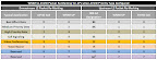
As stated previously, the access port configuration depends on the module in use. All of the 10/100 Ethernet series modules in Tables 1 and 2 have 1Q4T receive and 2Q2T transmit queue architectures. For modules in Table 1 the port is configured to trust the IP phone and not to trust the PC attached to the phone. For modules in Table 2 a workaround is used because these modules are unable to "trust" the CoS of incoming traffic. The workaround consists of using an access-control-list (ACL) policy to retain the CoS of the traffic. An access port also is configured to use output scheduling through multiple transmit queues.

To configure the interface for a module in Table 1,do the following:

Step 1. Select a port to configure.

6509-Access(config)#interface fastethernet 5/1

Step 2. Configure the port as a Layer 2 port in the access mode.

6509-Access(config-if)#switchport

6509-Access(config-if)#switchport mode access

Step 3. Define the voice VLAN.

6509-Access(config-if)#switchport voice vlan 111

Step 4. Define the data VLAN.

6509-Access(config-if)#switchport access vlan 11

Step 5. Configure the port as a host port.

6509-Access(config-if)#spanning-tree portfast

Step 6. Enable inline power.

6509-Access(config-if)#power inline auto

Step 7. Accept the incoming Layer 2 CoS. This lets the switch accept the phone marking of voice traffic at CoS = 5 and voice control traffic at CoS = 3 and enables input scheduling.

6509-Access(config-if)#mls qos trust cos

Step 8. Instruct the IP phone to rewrite the PC traffic to CoS = 0.

6509-Access(config-if)#mls qos trust extend cos 0

Step 9. Place CoS = 1 in queue 1 threshold 1.

6509-Access(config-if)#wrr-queue cos-map 1 1 1

Step 10. Place CoS = 0 in queue 1 threshold 2.

6509-Access(config-if)#wrr-queue cos-map 1 2 0

Step 11. Place CoS = 2, 3, 4, 6, and 7 in queue 2 threshold 1.

6509-Access(config-if)#wrr-queue cos-map 2 1 2 3 4 6 7

Step 12. Place CoS = 5 in queue 2 threshold 2.

6509-Access(config-if)#wrr-queue cos-map 2 2 5

Step 13. Modify the CoS-to-DSCP mapping. The recommended settings are DSCP = CS3 (24) for voice-over-IP (VoIP) control and DSCP = EF (46) for VoIP media traffic. To map the Layer 2 CoS correctly to these DSCP values, you must modify the switch default CoS-to-DSCP mappings. All CoS are shown though only 0, 3, and 5 are directly related to IPT.

6509-Access(config)#mls qos map cos-dscp 0 8 16 24 32 46 48 54

Note: CoS 3 and 5 are the 4th and 6th values, respectively.

To configure an interface on the modules listed in Table 2 do Steps 1 through 13 plus configure the following additional commands:

Step 1. Create an access list to match all traffic.

6509-Access(config)#access-list 100 permit ip any any

Step 2. Create a class for this traffic.

6509-Access(config)#class-map TRUST_COS_CLASS

6509-Access(config-cmap)#match access-group 100

6509-Access(config-cmap)#exit

Step 3. Create a policy to trust the CoS for the traffic in the class.

6509-Access(config)#policy-map TRUST_COS_POLICY

6509-Access(config-pmap)#class TRUST_COS_CLASS

6509-Access(config-pmap-c)#trust cos

6509-Access(config-pmap-c)#exit

Step 4. Apply the policy to the interface.

6509-Access(config)#int fa5/1

6509-Access(config-if)#service-policy input TRUST_COS_POLICY

CONFIGURING THE UPLINK TO THE DISTRIBUTION SWITCH

After you configure the access port queuing, you must also configure the uplink interfaces to the distribution, or core, switch. This involves enabling trust for Ethernet frames coming into the trunk port, enabling output scheduling, and manipulating the CoS-to-queue mapping entrance criteria, mapping the CoS values to the appropriate DSCP value.

This section includes information for two of the six types of queue structures: 1P2Q2T and 2Q2T.

Configuring an Uplink Port

Step 1. Accept incoming DSCP markings if incoming traffic is known to be properly marked at Layer 3. This is the preferred method.

6509-Access(config-if)#mls qos trust dscp

Alternate Step 1. Accept incoming CoS markings if incoming traffic is known to be properly marked at Layer 2 only.

6509-Access(config-if)#mls qos trust cos

Optional Step 2 (required when trusting CoS) Verify CoS-to-DSCP mapping. This should have been set in Step 10 in the interface configuration. Map CoS = 5 to DSCP = EF (46) and CoS = 3 to DSCP = CS3 (24).

6509-Access(config)#mls qos map cos-dscp 0 8 16 24 32 46 48 54

Configuring Transmit Queues

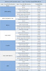
All CoS = 5 traffic (VoIP media) is placed into the egress interface priority queue on 1P2Q2T interfaces and queue 2 threshold 2 on 2Q2T interfaces by default upon enabling switchwide QoS. To follow QoS best practices, additional configuration of the CoS queue admission rules is needed to ensure that all other CoS traffic, and most importantly CoS = 3 (VoIP control), is placed into the correct queue. Separate configurations follow for 1P2Q2T and 2Q2T interfaces. For configuration of different interface queue structures, refer to other Cisco Catalyst 6500 QoS documentation.

Tweaking RRM parameters

I wasn't aware that there were so many variables that could be adjusted for RRM.

Chapter 10 Configuring Radio Resource Management 
  • config {802.11a | 802.11b} channel global auto 
  • config {802.11a | 802.11b} channel global once 
  • config advanced {802.11a | 802.11b} channel {add | delete} channel_number 
  • config advanced {802.11a | 802.11b} channel dca sensitivity {low | medium | high
  • config advanced {802.11a | 802.11b} channel dca anchor-time hour 
  • config advanced {802.11a | 802.11b} channel dca interval value
Radio Resource Management under Unified Wireless Networks  

RRM Tuning (IUWMS module 1) - by Jerome Henry * CCO login required

RRM and the Ripple Effect - good response by Jerome Henry * CCO login required

Authentication on WLCs, Layer 2 Solutions:

Excerpt below taken from Authentication on Wireless LAN Controllers Configuration Examples

Authentication on WLCs

The Cisco Unified Wireless Network (UWN) security solution bundles potentially complicated Layer 1, Layer 2, and Layer 3 802.11 Access Point (AP) security components into a simple policy manager that customizes system-wide security policies on a per-wireless LAN (WLAN) basis. The Cisco UWN security solution provides simple, unified, and systematic security management tools.
These security mechanisms can be implemented on WLCs.

Layer 1 Solutions

Restrict client access based on the number of consecutive failed attempts.

Layer 2 Solutions

None Authentication —When this option is selected from the Layer 2 Security menu, No Layer 2 authentication is performed on the WLAN. This is the same as the open authentication of the 802.11 standard.

Static WEP —With Static Wired Equivalent Privacy (WEP), all APs and client radio NICs on a particular WLAN must use the same encryption key. Each sending station encrypts the body of each frame with a WEP key before transmission, and the receiving station decrypts it using an identical key upon reception. 

802.1x —Configures the WLAN to use the 802.1x based authentication. The use of IEEE 802.1X offers an effective framework in order to authenticate and control user traffic to a protected network, as well as dynamically vary encryption keys. 802.1X ties a protocol called Extensible Authentication Protocol (EAP) to both the wired and WLAN media and supports multiple authentication methods.

Static WEP + 802.1x —This Layer 2 security setting enables both 802.1x and Static WEP. Clients can either use Static WEP or 802.1x authentication in order to connect to the network. 

Wi-Fi Protected Access (WPA) —WPA or WPA1 and WPA2 are standard-based security solutions from the Wi-Fi Alliance that provide data protection and access control for WLAN systems. WPA1 is compatible with the IEEE 802.11i standard but was implemented before the standard's ratification. WPA2 is the Wi-Fi Alliance's implementation of the ratified IEEE 802.11i standard. 

By default, WPA1 uses Temporal Key Integrity Protocol (TKIP) and message integrity check (MIC) for data protection. WPA2 uses the stronger Advanced Encryption Standard encryption algorithm using Counter Mode with Cipher Block Chaining Message Authentication Code Protocol (AES-CCMP). Both WPA1 and WPA2 use 802.1X for authenticated key management by default. However, these options are also available: PSK, CCKM, and CCKM+802.1x. If you select CCKM, Cisco only allows clients which support CCKM. If you select CCKM+802.1x, Cisco allows non-CCKM clients also.

CKIP —Cisco Key Integrity Protocol (CKIP) is a Cisco-proprietary security protocol for encrypting 802.11 media. CKIP improves 802.11 security in infrastructure mode using key permutation, MIC, and message sequence number. Software release 4.0 supports CKIP with static key. For this feature to operate correctly, you must enable Aironet information elements (IEs) for the WLAN. The CKIP settings specified in a WLAN are mandatory for any client that attempts to associate. If the WLAN is configured for both CKIP key permutation and MMH MIC, the client must support both. If the WLAN is configured for only one of these features, the client must support only this CKIP feature. WLCs only support static CKIP (like static WEP). WLCs do not support CKIP with 802.1x (dynamic CKIP).

Layer 3 Solutions

None—When this option is selected from the Layer 3 security menu, No Layer 3 authentication is performed on the WLAN.
Note: The configuration example for No Layer 3 authentication and No Layer 2 authentication is explained in the None Authentication section.

Web Policy (Web Authentication and Web Passthrough) —Web authentication is typically used by customers who want to deploy a guest-access network. In a guest-access network, there is initial username and password authentication, but security is not required for the subsequent traffic. Typical deployments can include "hot spot" locations, such as T-Mobile or Starbucks.

Web authentication for the Cisco WLC is done locally. You create an interface and then associate a WLAN/service set identifier (SSID) with that interface.
Web authentication provides simple authentication without a supplicant or client. Keep in mind that web authentication does not provide data encryption. Web authentication is typically used as simple guest access for either a "hot spot" or campus atmosphere where the only concern is the connectivity.

Web passthrough is a solution through which wireless users are redirected to an acceptable usage policy page without having to authenticate when they connect to the Internet. This redirection is taken care of by the WLC itself. The only requirement is to configure the WLC for web passthrough, which is basically web authentication without having to enter any credentials.

VPN Passthrough —VPN Passthrough is a feature which allows a client to establish a tunnel only with a specific VPN server. Therefore, if you need to securely access the configured VPN server as well as another VPN server or the Internet, this is not possible with VPN Passthrough enabled on the controller.
In the next sections, configuration examples are provided for each of the authentication mechanisms.

Syslog and your wireless infrastructure

I found an *ancient* Cisco PDF that covers syslog in as much detail as I could ever require..

Cisco ISP Essentials from 06/06/2001! - the section covering detailed syslogging is on page 22.


Detailed Logging

Keeping logs is a common and accepted operation practice. Interface status, security alerts, environmental conditions, CPU process hog and many other events on the router can be captured and analysed via UNIX syslog. Cisco System's IOS has the capability to do UNIX logging to a UNIX syslog server. The router syslog format is compatible with BSD UNIX syslog (now found as part of most Unix and Linux systems deployed today). The follow is a typical logging configuration for ISPs:

no logging console <-- Don’t send logs to the router console
logging buffered 16384 <-- 16Kbyte history buffer on router
logging trap debugging <-- Catch debugging level traps (i.e. everything)
logging facility local7 <-- Syslog facility on syslog server
logging 169.223.32.1 <-- IP address of your first syslog server
logging 169.223.45.8 <-- IP address of your second syslog server


!---- logging [server ip address]
!---- logging trap [warning]

Setting the logging parameters on a 4402 WLC:

From ccie(w)
 

IOS Bridge link with WPAv2 & AES

I finally found the right document that enabled me to setup a couple of 1242 IOS APs as a bridge link and use WPAv2 and AES encryption.

The document I used was the Wi-Fi Protected Access 2 (WPA 2) Configuration Example : LINK 

Here is a screen grab of the non-root bridge association statistics:
From ccie(w)
I used the config guide to setup the link via the GUI, and this is the pertinent CLI output for the Root Bridge.
aaa group server radius rad_eap
 server 192.168.200.10 auth-port 1812 acct-port 1813
!
aaa authentication login eap_methods group rad_eap
!
dot11 ssid Cisco
   vlan 200
   authentication network-eap eap_methods
   authentication key-management wpa
   authentication client username admin password 0 Cisco123
   infrastructure-ssid
!
interface Dot11Radio1
 no ip address
 no ip route-cache
 !
 encryption mode ciphers aes-ccm
 !
 encryption vlan 200 mode ciphers aes-ccm
 !
 ssid Cisco
 !
 !
 station-role root bridge
!--- for the non-root bridge: station-role non-root bridge
!--- for the non-root bridge: parent 1 [parent AP MAC address]
radius-server local
  no authentication eapfast
  no authentication mac
  nas 192.168.200.10 key 0 Cisco123
  user admin password 0 Cisco123
!
radius-server host 192.168.200.10 auth-port 1812 acct-port 1813 key 0 Cisco123

Saturday, February 6, 2010

WLC L2 & L3 Security Compatibility Matrix

Wireless LAN Controller Layer 2 – Layer 3 Security Compatibility Matrix

I liked the charts in this document, but the formatting in this PDF is horrendous.

Layer 2 Security Mechanism

From ccie(w)


Layer 3 Security Mechanism (for WLAN)

From ccie(w)


Layer 3 Security Mechanism (for Guest LAN)

From ccie(w)


Wireless LAN Controller Layer 2 – Layer 3 Security Compatibility Matrix
From ccie(w)